
Component Catalog Measurement Reference
Accurate component dimensions and center-of-gravity locations improve the quality of Precision Arrow Builder's arrow calculations and optimization results. Use this page as a practical reference when entering measured component data into the component catalog.
Part of the Technical Reference, alongside Terminology. For how these measurements fit into a finished arrow, see Arrow Components.
How to use this reference
Find the component you are measuring, take the measurement from the datum shown for that component, and apply the sign convention exactly as described. Using the same datum and signs for every component keeps your recorded lengths and center-of-gravity locations comparable, which is what front-of-center calculations depend on.
Shared conventions
- The reference location is
0.0. - The reference is the point or surface where the component mates with the component to which it is attached.
- Measurements are taken along the arrow's longitudinal axis.
- Locations are signed (+/-) values. Enter 0.0 if unknown.
- Locations forward of the reference are positive.
- Locations rearward of the reference are negative.
- Lengths are nonnegative values. Enter 0.0 if unknown.
- Center-of-gravity location is the signed axial distance from the datum to the balance point.
Component type
Points
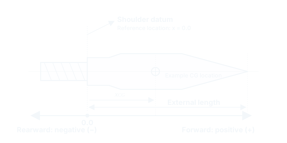
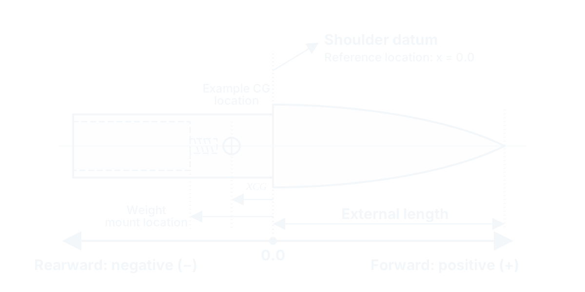
The examples show generic screw-in and glue-in points. Point construction varies, but the same datum and sign conventions apply to the component you measure.
Measurement reference
The shoulder that seats against the adapter, insert, shaft, or other receiving component is the 0.0 reference surface. The point tip is forward and positive; the portion installed into the receiving component is rearward and negative.
Center-of-gravity location
The center-of-gravity of a screw-in point is typically forward of the datum, while some glue-in points have a rearward center-of-gravity. Measure the actual component rather than assuming the sign or location.
Catalog fields
- Center-of-gravity location
Location of the balance point relative to the shoulder datum.
Sign convention: Forward of the shoulder datum is positive; rearward into the threaded shank or glue-in section is negative.
Purpose: Used in front-of-center calculations.
- External length
Distance from the shoulder datum to the tip of the point.
Sign convention: Nonnegative value.
Purpose: Used to calculate overall arrow length.
- Weight mount location
Location of the weight mating surface relative to the point shoulder datum. Use 0.0 if it does not accept weights.
Sign convention: Forward of the shoulder datum is positive; rearward into the glue-in section is negative.
Purpose: Used in front-of-center calculations.
Component type
Point adapters
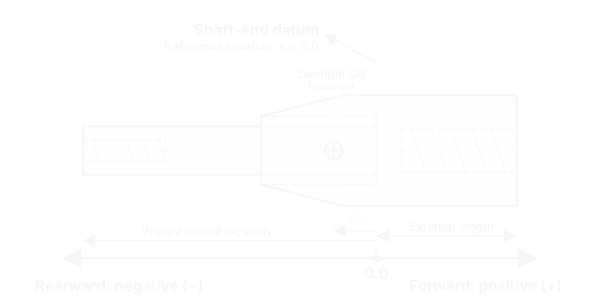
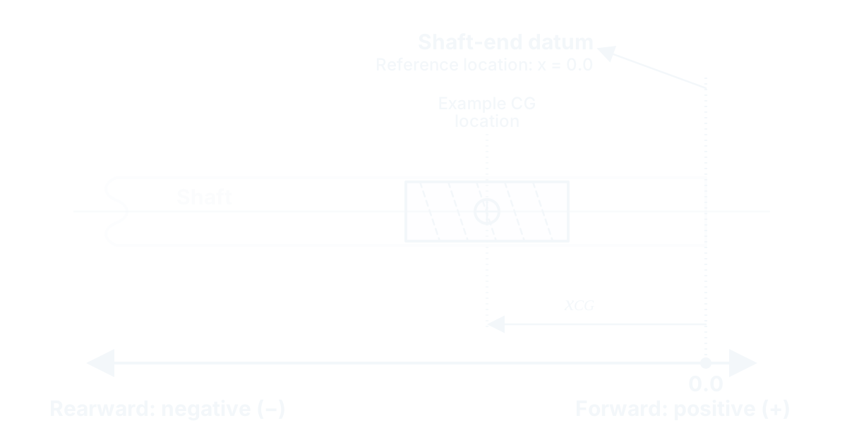
The examples show two point adapter situations that can be difficult to measure: a halfout with the shaft end recessed inside the adapter, and a hidden insert recessed in the shaft when installed. Insert, outsert, and halfout construction varies, but the same datum and sign conventions apply to the component you measure.
Measurement reference
The end of the shaft when the insert, outsert, or halfout is installed is the 0.0 reference surface.
Center-of-gravity location
The center-of-gravity of a point adapter can be forward or rearward of the shaft end when installed.
Catalog fields
- Center-of-gravity location
Location of the balance point relative to the shaft end datum when installed.
Sign convention: Forward of the shaft end datum is positive; rearward into the shaft is negative.
Purpose: Used in front-of-center calculations.
- External length
Length added to the end of the shaft. Can be 0.0 for hidden inserts.
Sign convention: Nonnegative value.
Purpose: Used to calculate overall arrow length and front-of-center calculations.
- Weight mount location
Location of the weight mating surface relative to the shaft end datum when installed. Enter 0.0 if it does not accept weights.
Sign convention: Rearward into the shaft is negative. For the illustrated installation, this value is expected to be less than or equal to 0.0.
Purpose: Used in front-of-center calculations.
- Shaft description
Identifies the intended shaft(s) it is designed for.
Purpose: Used to identify variations of the same model.
Component type
Front collars
The example shows a generic front collar. Construction varies, but the same datum and sign conventions apply to the component you measure.
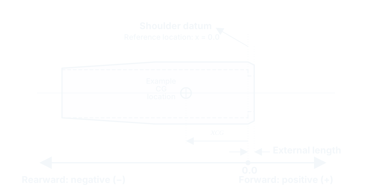
Measurement reference
The end of the shaft when the collar is installed, typically the internal shoulder on the collar, is the 0.0 reference surface.
Center-of-gravity location
The center-of-gravity of a front collar is typically aft of the shaft end when installed and therefore negative.
Catalog fields
- Center-of-gravity location
Location of the balance point relative to the shoulder or shaft end datum when installed.
Sign convention: Forward of the shoulder datum is positive; rearward is negative.
Purpose: Used in front-of-center calculations.
- External length
Length added to the end of the shaft.
Sign convention: Nonnegative value.
Purpose: Used to calculate overall arrow length and front-of-center calculations.
- Shaft description
Identifies the intended shaft(s) it is designed for.
Purpose: Used to identify variations of the same model.
Component type
Nock collars
The example shows a generic nock collar. Construction varies, but the same datum and sign conventions apply to the component you measure.
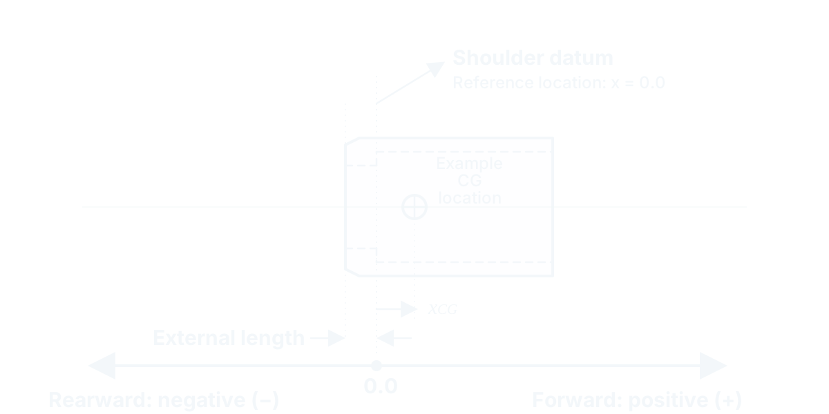
Measurement reference
The end of the shaft when the collar is installed, typically the internal shoulder on the collar, is the 0.0 reference surface.
Center-of-gravity location
The center-of-gravity of a nock collar is typically forward of the shaft end when installed and therefore positive.
Catalog fields
- Center-of-gravity location
Location of the balance point relative to the shoulder or shaft end datum when installed.
Sign convention: Forward of the shoulder datum is positive; rearward is negative.
Purpose: Used in front-of-center calculations.
- External length
Length added to the end of the shaft.
Sign convention: Nonnegative value.
Purpose: Used to calculate overall arrow length and front-of-center calculations.
- Shaft description
Identifies the intended shaft(s) it is designed for.
Purpose: Used to identify variations of the same model.
Component type
Nocks
The example shows a generic press-fit nock. Nock construction varies, but the same datum and sign conventions apply to the component you measure.
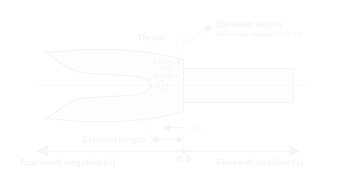
Measurement reference
The shoulder that seats against the adapter, collar or shaft is the 0.0 reference surface.
Center-of-gravity location
The center-of-gravity of a pin nock is typically rearward of the datum and therefore negative. The center-of-gravity of a press-fit nock is also typically rearward of the datum, while some press-fit nocks, particularly lighted nocks, may have a forward center-of-gravity. Measure the actual component rather than assuming the sign or location.
Catalog fields
- Center-of-gravity location
Location of the balance point relative to the shoulder datum.
Sign convention: Forward of the shoulder datum is positive; rearward is negative.
Purpose: Used in front-of-center calculations.
- External length
Distance from the shoulder datum to the throat of the nock.
Sign convention: Nonnegative value.
Purpose: Used to calculate overall arrow length.
- Size description
Size of the shaft it is designed for.
Purpose: Used to identify variations of the same model.
Component type
Nock adapters
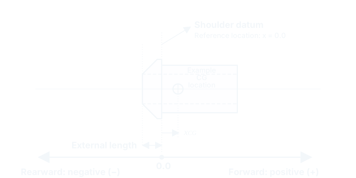
The examples show two of the most common adapters, pin nock adapters and bushings. Construction varies, but the same datum and sign conventions apply to the component you measure.
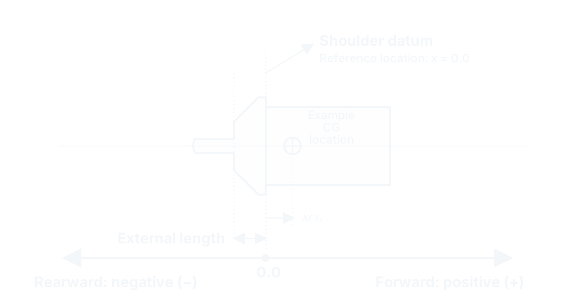
Measurement reference
The end of the shaft when the adapter is installed, typically the shoulder on the adapter, is the 0.0 reference surface.
Center-of-gravity location
The center-of-gravity of a nock adapter can be forward or rearward of the shaft end when installed.
Catalog fields
- Center-of-gravity location
Location of the balance point relative to the shoulder or shaft end datum when installed.
Sign convention: Forward of the shoulder datum is positive; rearward is negative.
Purpose: Used in front-of-center calculations.
- External length
Length added to the end of the shaft.
Sign convention: Nonnegative value.
Purpose: Used to calculate overall arrow length and front-of-center calculations.
- Shaft description
Identifies the intended shaft(s) it is designed for.
Purpose: Used to identify variations of the same model.
Component type
Fletching
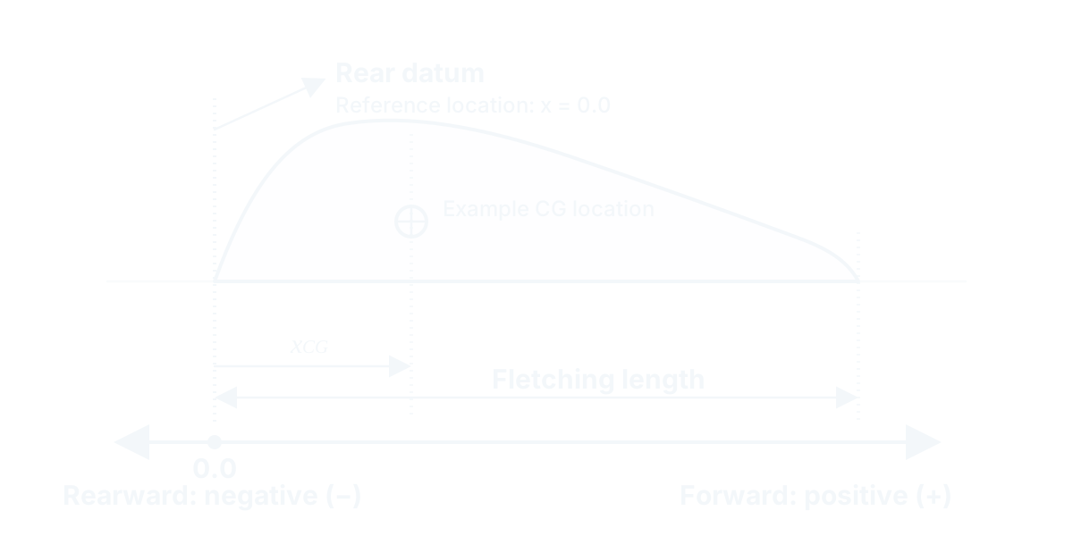
The example shows a generic fletching. Fletching construction varies, but the same datum and sign conventions apply to the component you measure.
Measurement reference
The rear of the fletching is the 0.0 reference surface.
Center-of-gravity location
The center-of-gravity of fletching is forward of the rear datum and therefore nonnegative. Measure the actual component rather than assuming the location.
Catalog fields
- Center-of-gravity location
Location of the balance point relative to the rear datum.
Sign convention: Forward of the rear datum is positive. Center-of-gravity location is generally nonnegative for the measured component.
Purpose: Used in front-of-center calculations.
- Length
Total length of the fletching.
Sign convention: Nonnegative value.
Purpose: Used to identify variations of the same model.
Component type
Weights
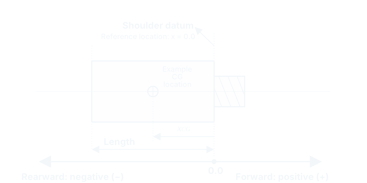
The example shows a generic weight. Construction varies, but the same datum and sign conventions apply to the component you measure.
Measurement reference
The shoulder on the front that rests against the point or point adapter is the 0.0 reference surface.
Center-of-gravity location
The center-of-gravity of a weight is less than or equal to 0.0 for the illustrated installation. Measure the actual component rather than assuming the location.
Catalog fields
- Center-of-gravity location
Location of the balance point relative to the shoulder.
Sign convention: Forward of the shoulder datum is positive; rearward is negative.
Purpose: Used in front-of-center calculations.
- Length
Length of the weight, not including the threaded portion.
Sign convention: Nonnegative value.
Purpose: Used in front-of-center calculations.
Related resources
How total arrow weight and front-of-center are calculated, and which measurements each calculation needs.
How each component contributes to a finished arrow's weight and balance, and why components vary.
Reference
Plain-language definitions of FOC, GPI, extreme spread, and other arrow-building terms.
How measured component details support more consistent, matched arrow sets.